

System Architecture Overview
Dalus provides a complete canvas for modeling complex systems with hierarchical organization. The left sidebar shows your model hierarchy, making it easy to navigate between different levels of your system. Toggle between different views to focus on structural elements, behaviors, or states.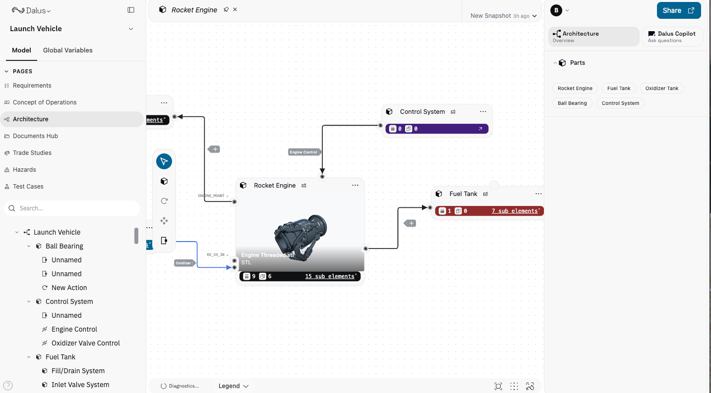
What are Parts
Parts are the fundamental building blocks of your system—representing physical components, logical modules, or any architectural element. Each part can contain nested sub-parts, creating a hierarchical decomposition of your system. Parts connect to other parts through ports and can have attributes (variables) that define their properties.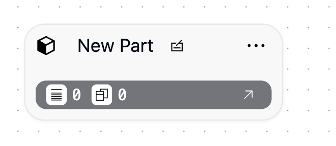
- Represent physical components (sensors, actuators, processors) or logical modules (software components, subsystems)
- Can be nested to create hierarchical system breakdowns
- Connect to other parts via ports and interfaces
- Can have attributes assigned to capture properties like mass, power consumption, or dimensions
- Can be linked to requirements for traceability
Creating Parts
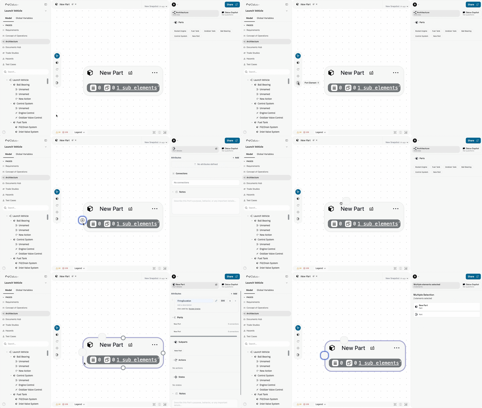
Create parts using the toolbar on the left side of the canvas or keyboard shortcuts: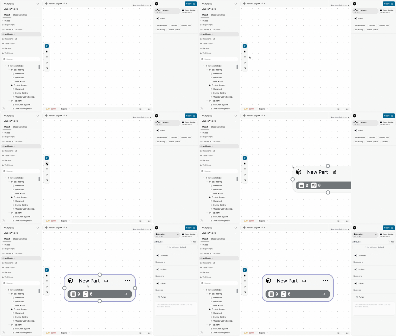
Part Properties and Attributes
When you select a part, the right sidebar displays all its properties:- Label: The part’s display name
- Description: Detailed description of the part’s purpose and function
- Attributes: Variables assigned to the part (mass, dimensions, power ratings, etc.)
- Sub-Parts: Nested parts contained within this part
- Ports: Connection points defined on this part
- Actions: Behaviors and computations associated with this part
- States: Operational modes and conditions
- Notes: Additional documentation
Adding Attributes
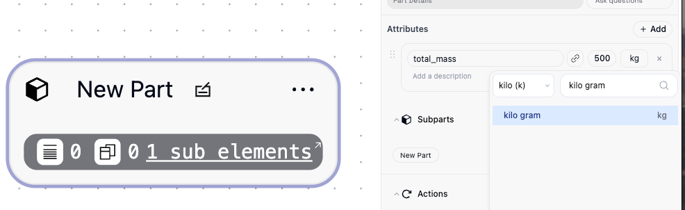
Attributes are variables that capture quantitative properties of a part. Click Add Attribute in the right sidebar to create new attributes:- Provide a descriptive name (use lowercase snake_case, e.g.,
total_mass,power_consumption) - Set the value and expression
- Specify the unit (meters, kilograms, watts, etc.)
- Optionally add a prefix for SI units (kilo, mega, milli)
Linking Existing Variables
Instead of creating a new attribute, you can link to an existing variable from anywhere in your model. Click the link icon next to the attribute field to open the variable search. Search by name or browse through available variables—including attributes from other parts, action outputs, and interface connections. Select a variable to link it directly to your part.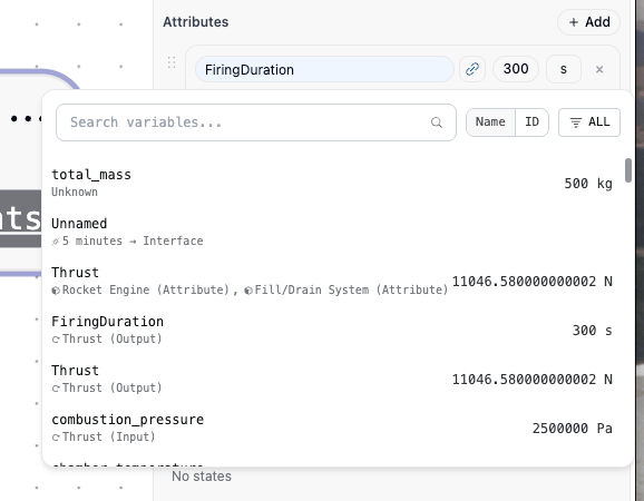
Adding Visuals to Parts
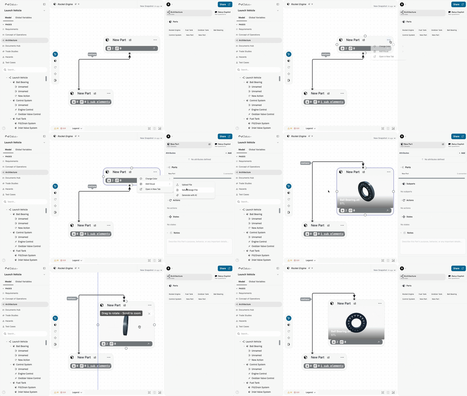
Enhance your parts with visual representations to make your model more intuitive and recognizable. Right-click on a part node and select Add Visual to attach an image. You can:- Upload an image: Add a custom image file (PNG, JPG, SVG) to represent the component
- Choose from the library: Select from previously uploaded images in your workspace
- Use AI generation: Generate an image using AI based on a description of your part
- Link from URL: Reference an external image by URL
What are Ports
Ports define connection points on parts where interfaces attach. They represent the boundary of a part—where information, energy, or matter flows in or out. Every connection between parts must go through ports.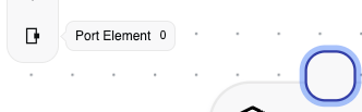
- Always belong to a parent part
- Snap to part edges for clean visual organization
- Can be inputs, outputs, or bidirectional
- Multiple ports can exist on a single part
- Serve as anchors for interface connections
Creating Ports
Create ports using these methods:
Ports automatically snap to the edges of parts. Position them logically—inputs on one side, outputs on another—to create readable diagrams.
What are Interfaces
Interfaces are edges that connect two ports, defining the relationship and data flow between parts. Each interface can contain multiple connections that specify exactly what flows between the connected parts. Interface characteristics:- Connect exactly two ports (source and target)
- Can contain multiple connections of different types
- Support color grouping for visual organization
- Can be saved as templates for reuse
Creating Interfaces
To create an interface:- Click and drag from one port
- Connect to another port on a different part
- Release to create the interface edge
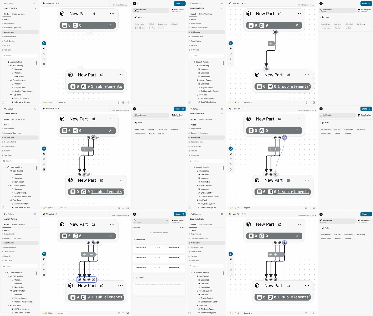
Ports belonging to the same part cannot be connected to each other. Interfaces always connect ports on different parts.
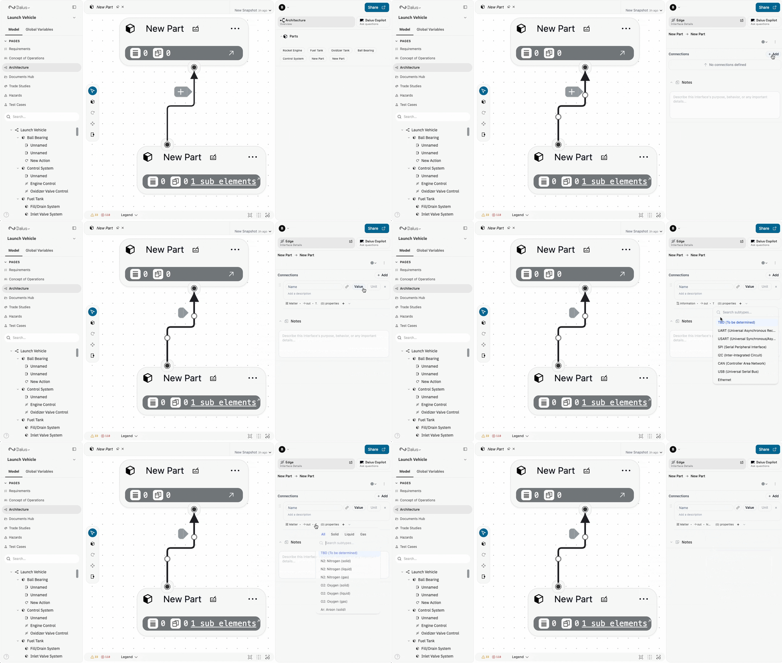
Creating Connections
Connections define the specific flows within interfaces. Each connection specifies:- Name: Descriptive name for the flow (lowercase snake_case)
- Type: The category of flow
- Direction:
in,out, orboth - Variable: The quantitative value being transferred
- Properties: Additional variables for secondary quantities
Connection Types
Dalus supports five primary connection types:
Each type can have subtypes for more specific categorization (e.g., Energy → Electrical, Energy → Mechanical).
Connection Variables and Properties
Every connection has:- Primary Variable (
variableId): The main quantity being transferred (e.g., electrical current in amps) - Properties (
propertyIds): Secondary quantities that characterize the flow (e.g., voltage, frequency)
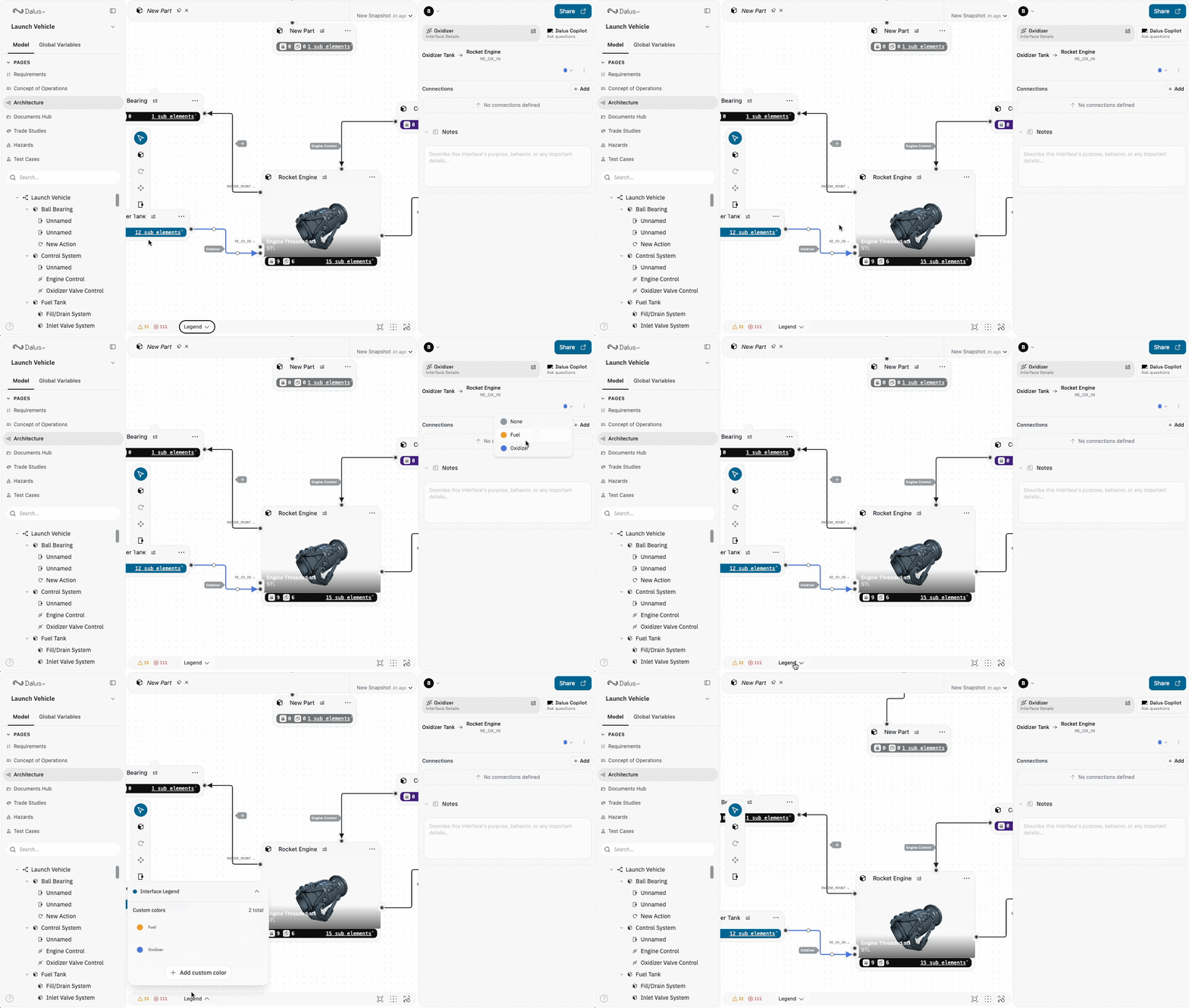
Color Groups
Organize complex interfaces using color groups for visual coding. Assign colors to related flows to make large systems easier to understand and navigate. Best practices for color coding:- Use consistent colors across your model for similar flow types
- Group related connections under the same color
- Choose high-contrast colors for critical interfaces
- Document your color scheme for team consistency
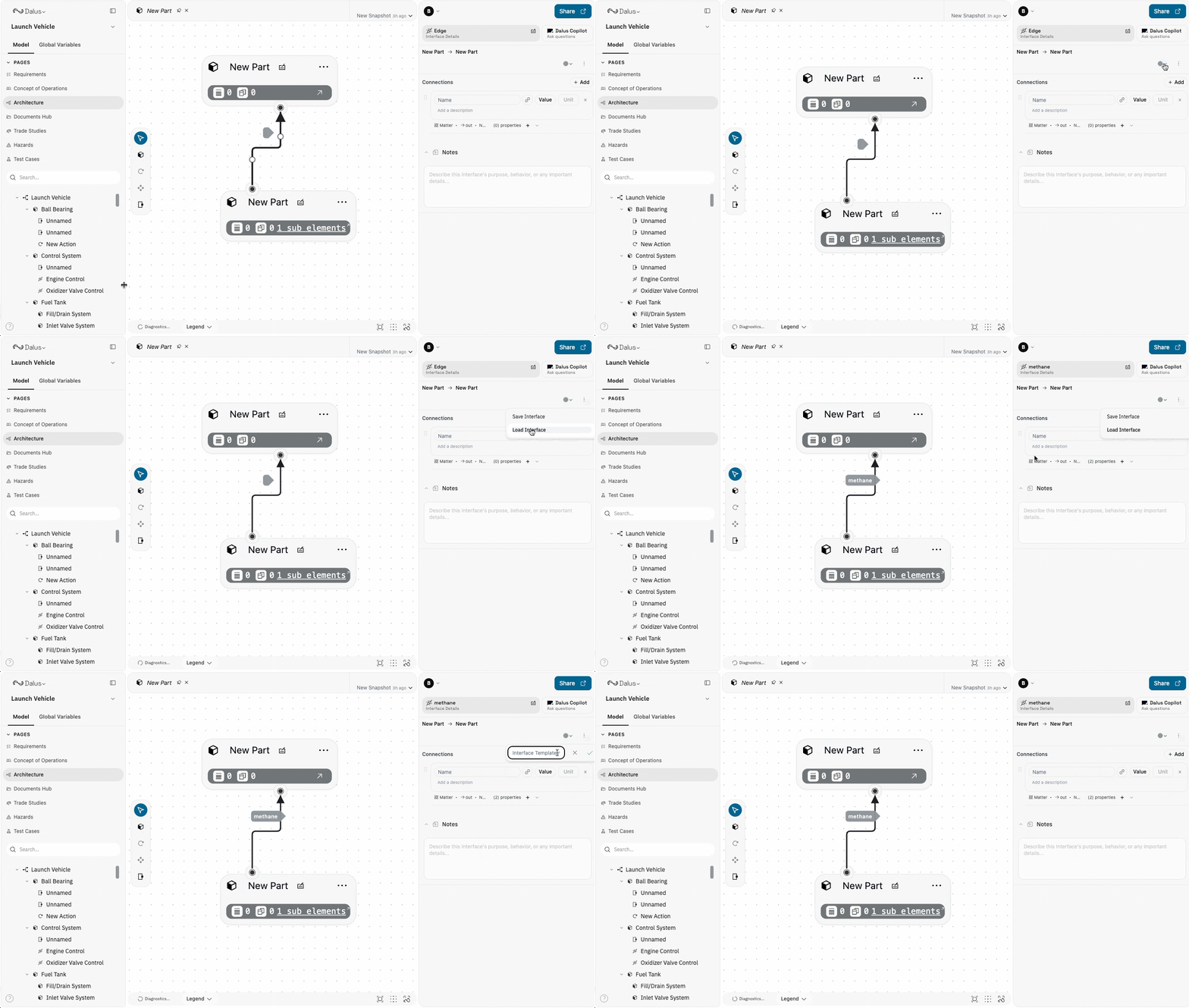
Interface Templates
Save frequently used interface configurations as templates for reuse across your models. Build a library of standard interface types for your domain to maintain consistency. To save a template:- Configure an interface with all desired connections
- Click the Save Template option
- Provide a descriptive name
- Select an interface
- Click Load Template
- Choose from your saved templates
Navigating Hierarchical Models
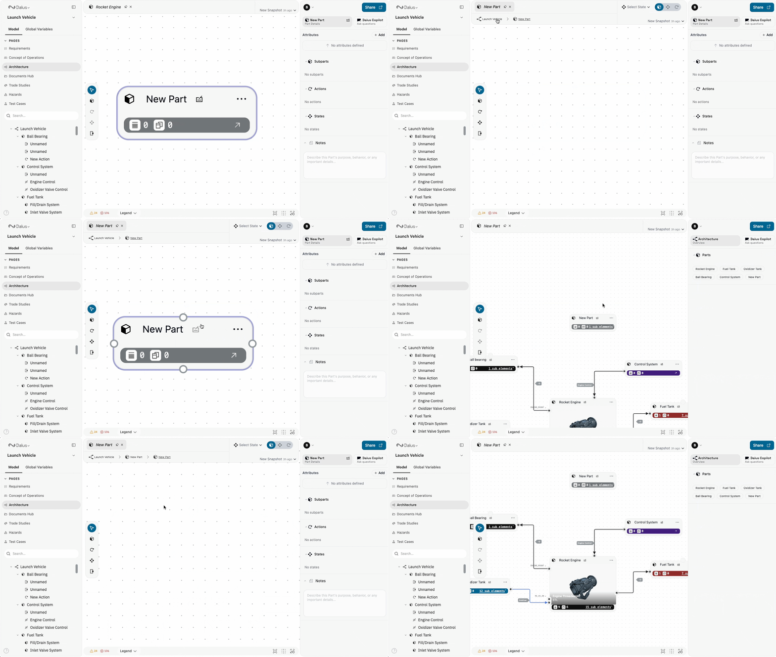
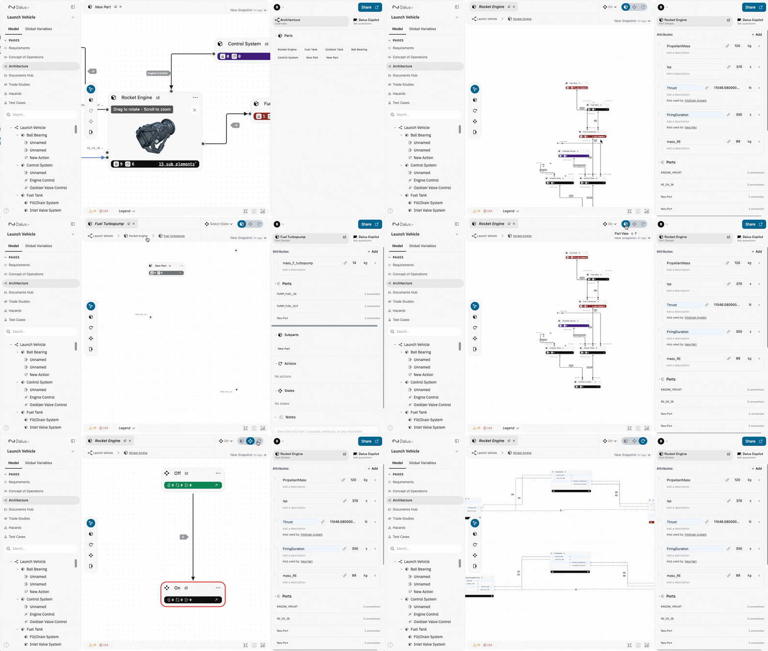
Dalus supports deep hierarchical nesting. Navigate effectively using:Drill-Down Navigation
- Double-click a part to enter it and view its internal structure
- The tab header shows breadcrumb navigation for your current location
- Click any breadcrumb to jump back to that level
View Modes
Toggle view modes to focus on different aspects:- Part View: Show structural elements (Parts, Ports, Interfaces)
- State View: Show state machines (States, Transitions)
- Action View: Show behaviors (Actions, Signals)
Left Sidebar Hierarchy
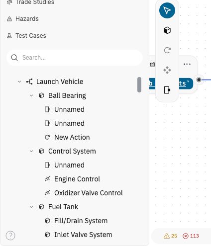
The model tree in the left sidebar provides:- Expandable/collapsible hierarchy
- Filter by element type
- Quick navigation to any element
- Search across all elements
Linking Parts to Requirements
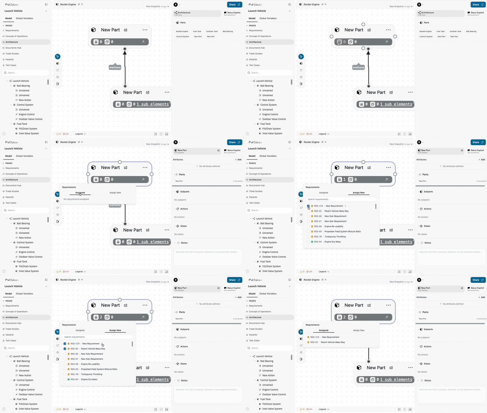
Parts can be assigned to requirements for complete traceability:- Open a requirement in the Requirements page
- Use the Assigned Systems menu to link parts
- Assignments appear as badges on both the requirement and part
Keyboard Shortcuts
Master these shortcuts for efficient structural modeling:Copy, Paste, and Duplication
Duplicate parts and their internal structure:- Select one or more parts (use
ShiftorCmd/Ctrl + Clickfor multi-select) - Copy with
Cmd/Ctrl + C - Paste with
Cmd/Ctrl + V
- All nested sub-parts
- Ports and their positions
- Internal interfaces and connections
- Attributes and variables
- Associated actions and states
Using AI for Structural Modeling
The Dalus AI Copilot accelerates structural modeling tasks:Subsystem Decomposition
Ask Copilot to break down a part into its constituent subsystems:- “Break down the Power System into its subsystems”
- “Create a functional decomposition of the Flight Computer”
Interface Generation
Let AI create interfaces between subsystems:- “Create interfaces between the subsystems of the Propulsion Module”
- “Add connections for power and data between these components”
Architecture from Requirements
Generate structural elements from requirement statements:- “Create parts to satisfy these interface requirements”
- “What subsystems are needed to meet the performance requirements?”
Model Queries
Ask questions about your architecture:- “What parts receive power from the Main Bus?”
- “Show me all interfaces that carry thermal data”
Collaboration
Dalus supports real-time collaboration on structural models:- Live Cursors: See where other team members are working
- Simultaneous Editing: Multiple users can edit different parts of the model
- Automatic Conflict Resolution: System handles concurrent edits gracefully
- Snapshots: Save model states for version tracking
Essential Tips
- Plan your hierarchy first: Sketch the high-level decomposition before diving into details
- Use consistent naming: Establish naming conventions for parts, ports, and interfaces
- Model incrementally: Build and validate small sections before connecting them
- Leverage templates: Save common interface patterns as templates
- Document as you go: Use descriptions and notes to capture design rationale
- Link to requirements early: Establish traceability while the design intent is fresh
- Use color coding: Develop a consistent color scheme for interface types
- Keep ports organized: Position inputs and outputs consistently across parts