

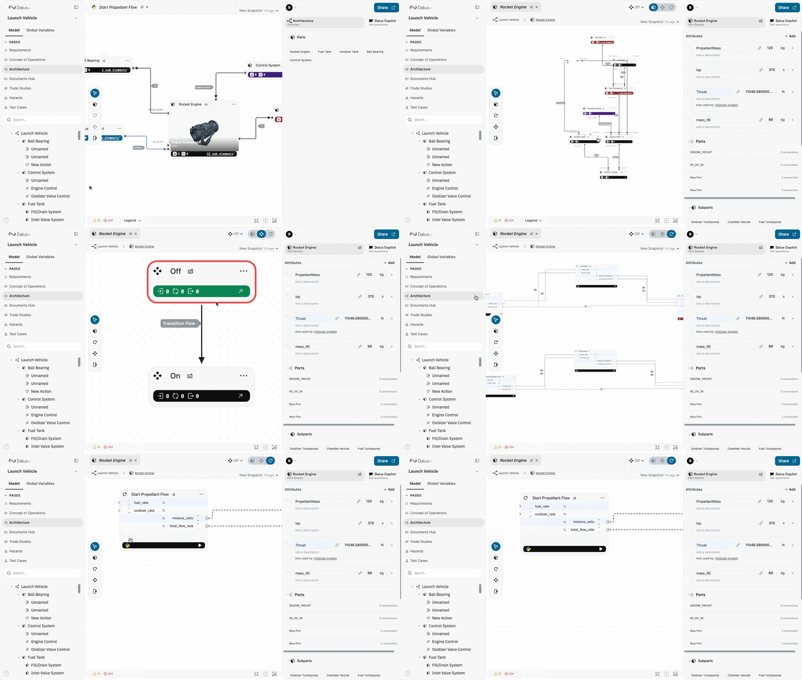
Behavior Modeling Overview
Dalus provides a complete canvas for modeling dynamic system behavior with executable elements. Actions perform computations and generate outputs, while state machines orchestrate when and how actions execute based on system conditions. Key behavioral elements:- Actions: Executable computations with Python scripts
- Signals: Data flow connections between actions
- States: Operational modes and conditions
- Transitions: Rules for changing between states
To access all three view modes (Part View, Action View, and State View), you must navigate at least one level down from the root. Double-click a part to enter it—the view toggles will then appear in the toolbar, allowing you to switch between structural, action, and state views.
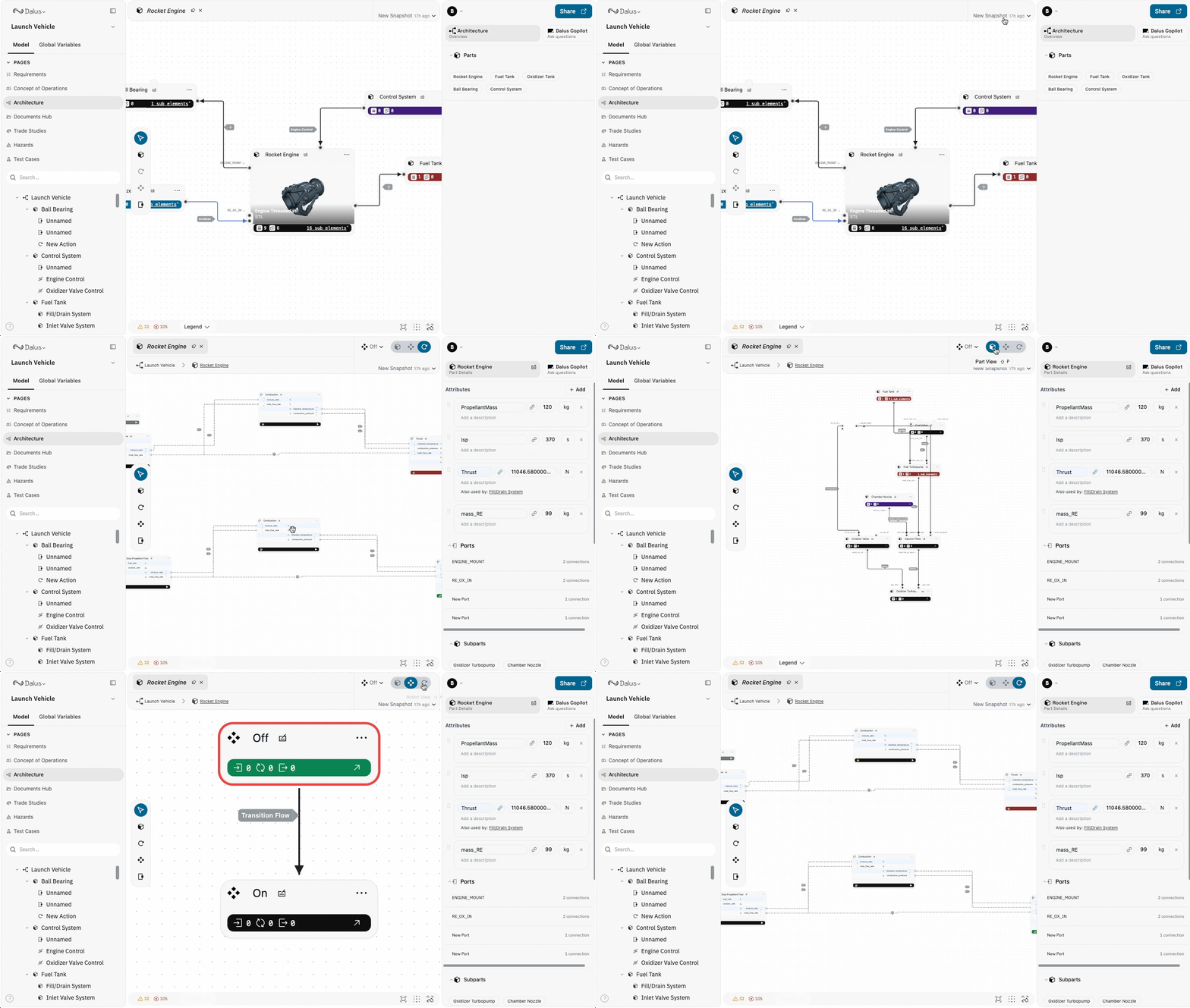
What are Action Nodes
Action nodes are executable elements that perform computations, process data, or trigger system behaviors. Each action contains a Python script that can:- Read input variables from connected actions
- Perform calculations and data processing
- Produce output variables for downstream actions
- Generate visualizations (tables, charts)
Creating Action Nodes
Create action nodes using the toolbar or keyboard:Actions must be created inside a Part. They cannot exist at the root level of your model.
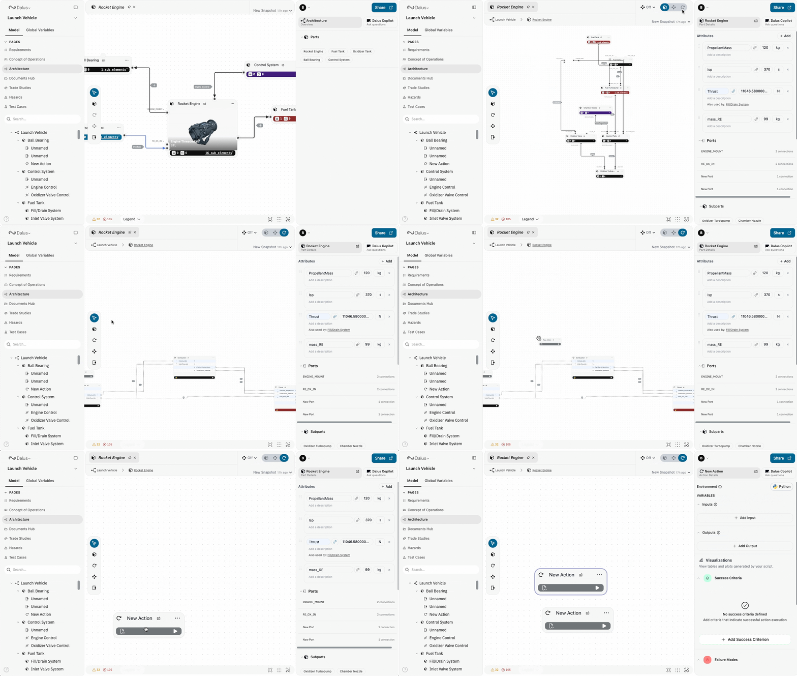
Calculate_Thrust, Process_Sensor_Data, Validate_Inputs).
Double-click any action to open it in a new tab and access the full script editor.
Action Properties
When you select an action, the right sidebar displays:- Label: The action’s display name
- Description: Explanation of what the action computes
- Input Variables: Data inputs received from other actions
- Output Variables: Data outputs produced for other actions
- Script: The Python code that executes
- Visualizations: Charts and tables generated by the script
- Notes: Additional documentation
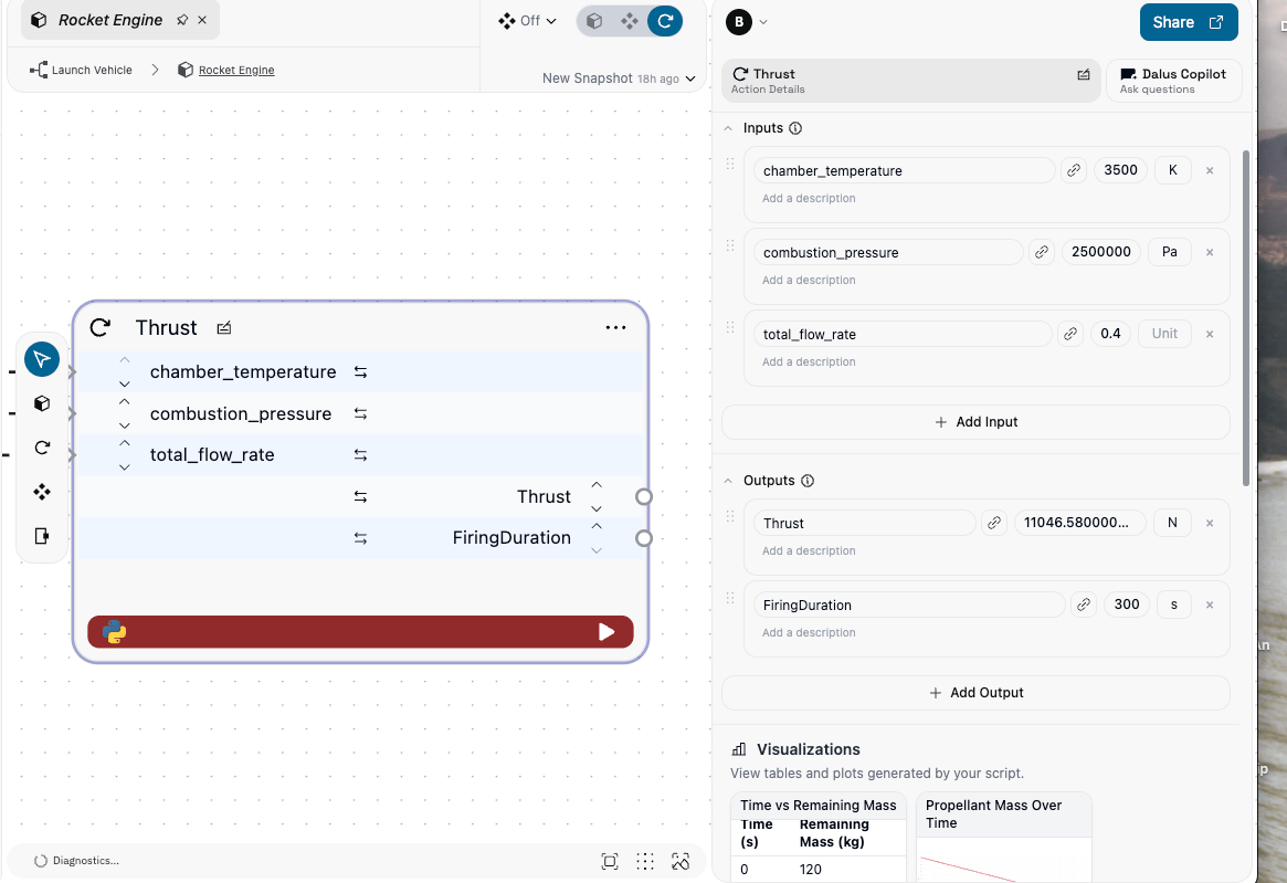
Input and Output Variables
Actions communicate through variables: Input Variables:- Receive data from upstream actions via signal edges
- Must specify name, type, and unit
- Provide default values when appropriate for standalone testing
- Produce data for downstream actions
- Must specify name and unit (value is computed at runtime)
- Connect to inputs of other actions via signals
Always specify units for variables representing physical quantities. This ensures dimensional consistency and enables unit-aware calculations.
Script Editor Interface
The script editor provides a comprehensive environment for writing and executing Python code. Open it by double-clicking on an action node or by clicking the script icon in the right sidebar when an action is selected.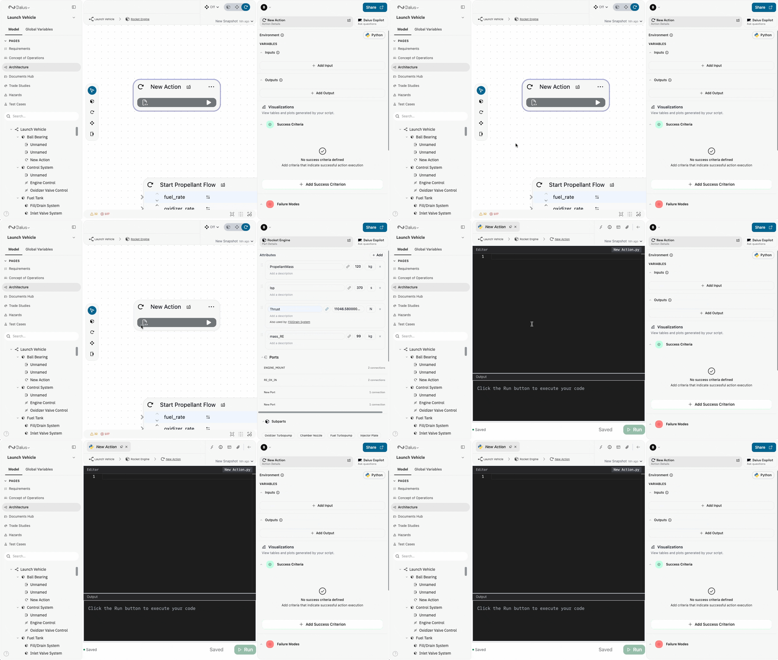
Editor Layout
- Code Area: Write Python scripts with syntax highlighting
- Variables Panel: Search and reference model variables
- Output Console: View execution results and errors
- Run Controls: Execute scripts and monitor status
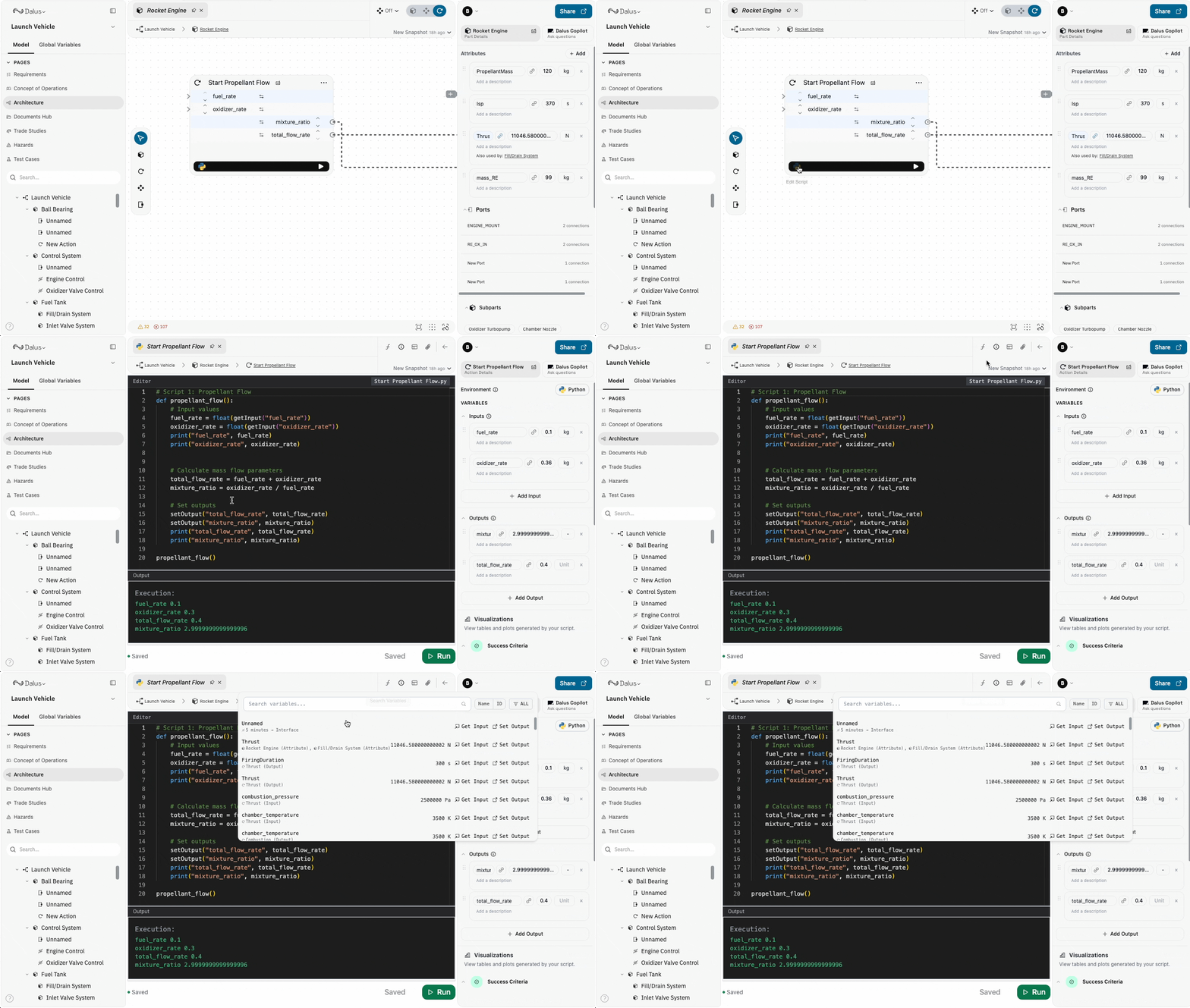
Writing Python Scripts
Write Python code directly in the editor. Scripts have access to:- Standard Python libraries
- Input variables by their IDs
- Model variables via the search interface
Using Variables in Scripts
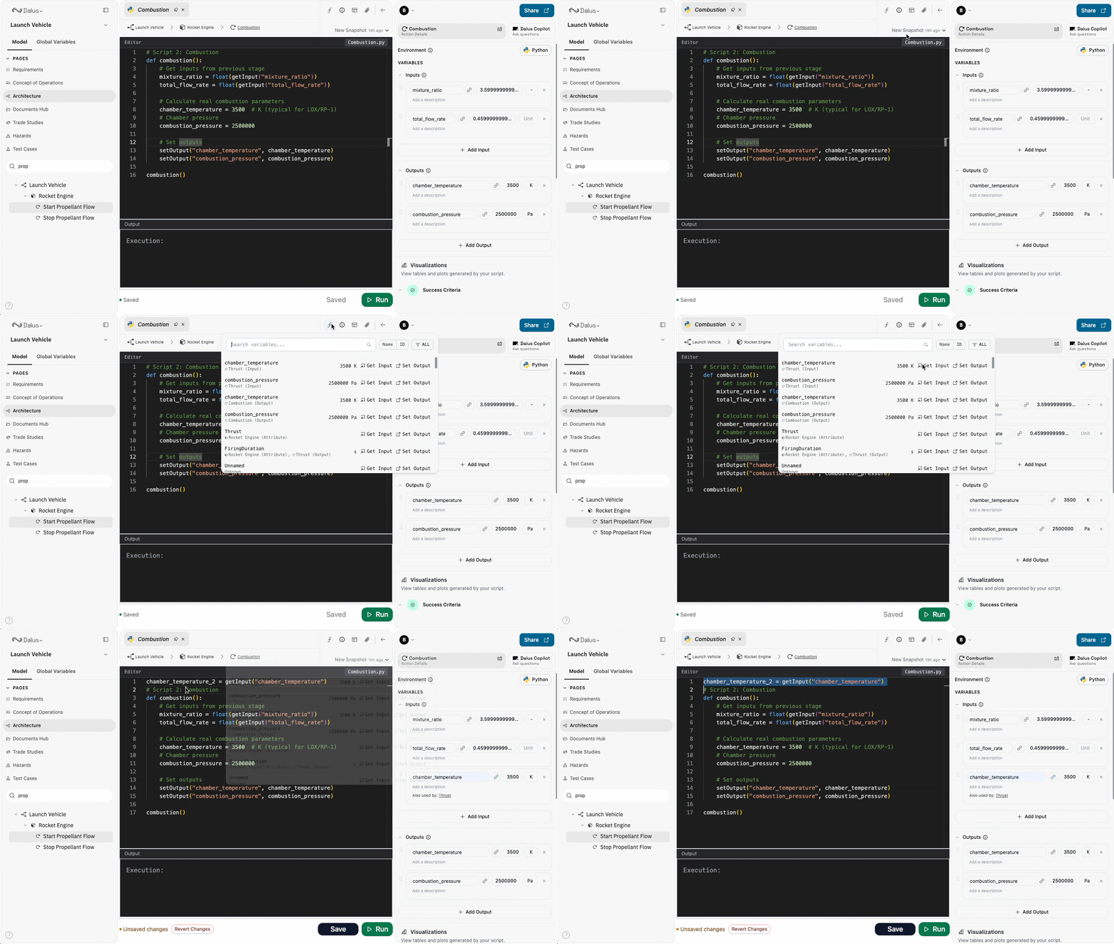
Access any variable in your model through the Variables panel:- Click the Variables button in the script editor to open the search panel
- Search for variables by name across your entire model
- Choose the action to insert:
- Get Input: Insert a
getInput()call to read the variable value - Set Output: Insert a
setOutput()call to write a value - Copy Name: Copy the variable name to use manually in your script
- Get Input: Insert a
- The selected code snippet is automatically inserted at your cursor position
Running Scripts
Execute scripts directly from the editor:- Click the Run button or use the keyboard shortcut
- Monitor execution status in the console
- View outputs and any error messages
- Check generated visualizations in the right sidebar
Data Visualizations
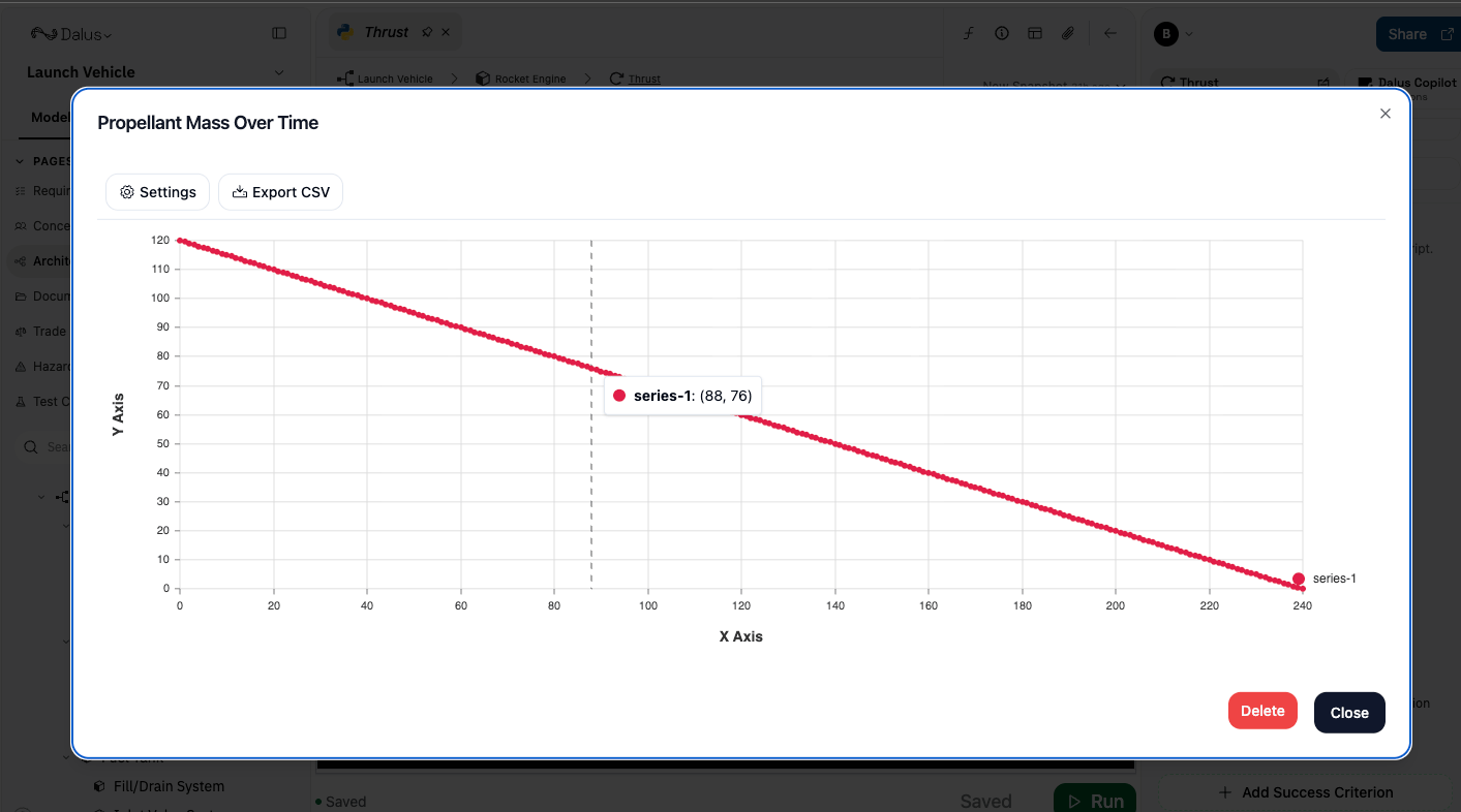
Actions can generate visualizations that appear in the right sidebar after execution:
To create visualizations, use the visualization functions in your script:
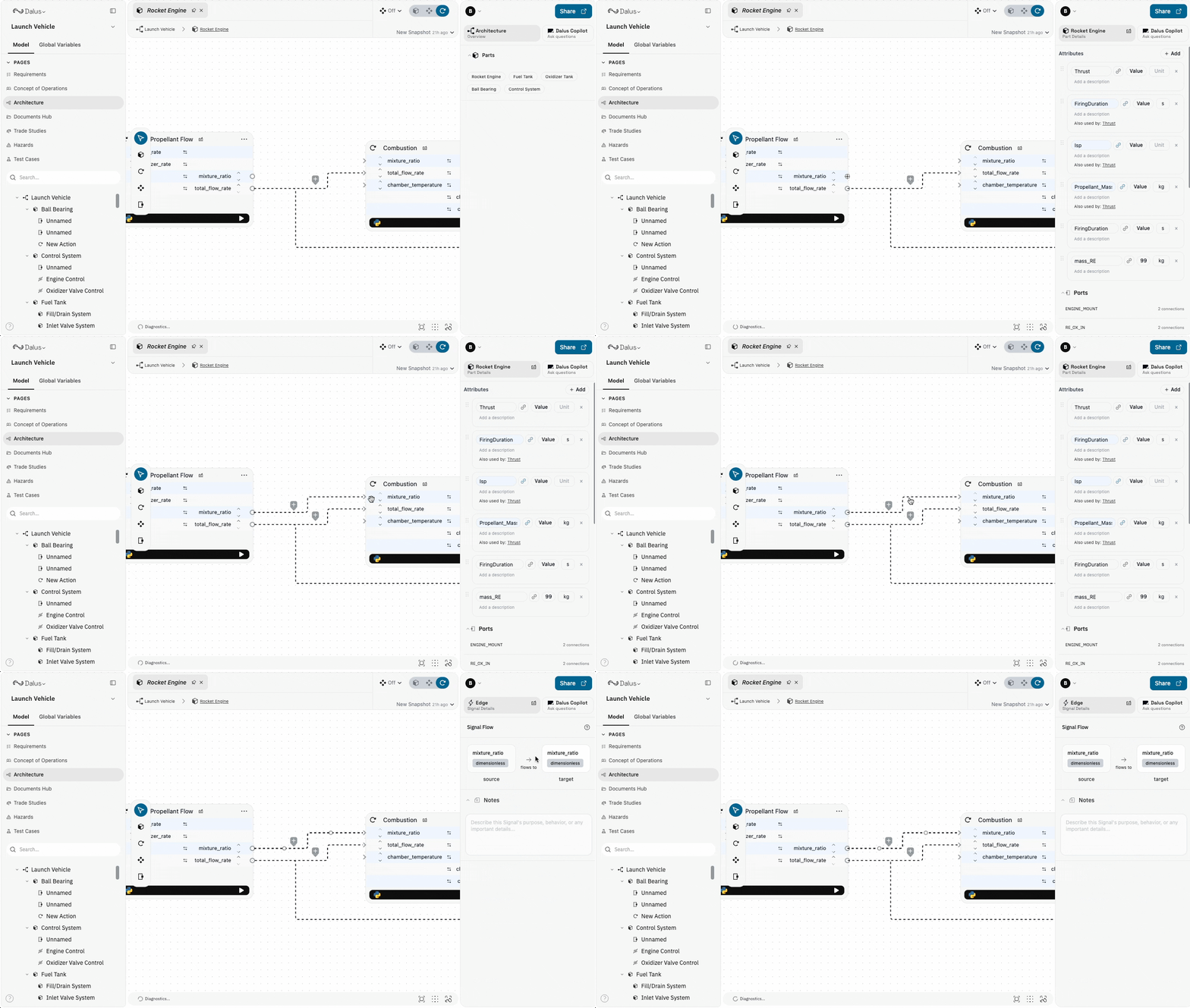
Creating Signal Edges
Signal edges connect action nodes to transfer data. They represent the flow of variables from one action’s outputs to another action’s inputs.Creating Signals
- Click and drag from an output handle on one action
- Connect to an input handle on another action
- The signal edge links the corresponding variables
Signal Semantics
When connecting actions, match variables by semantic meaning, not position:Critical: Always examine variable names and units when creating signals. An altitude output should connect to an altitude or height input, not to an unrelated variable like power_draw.
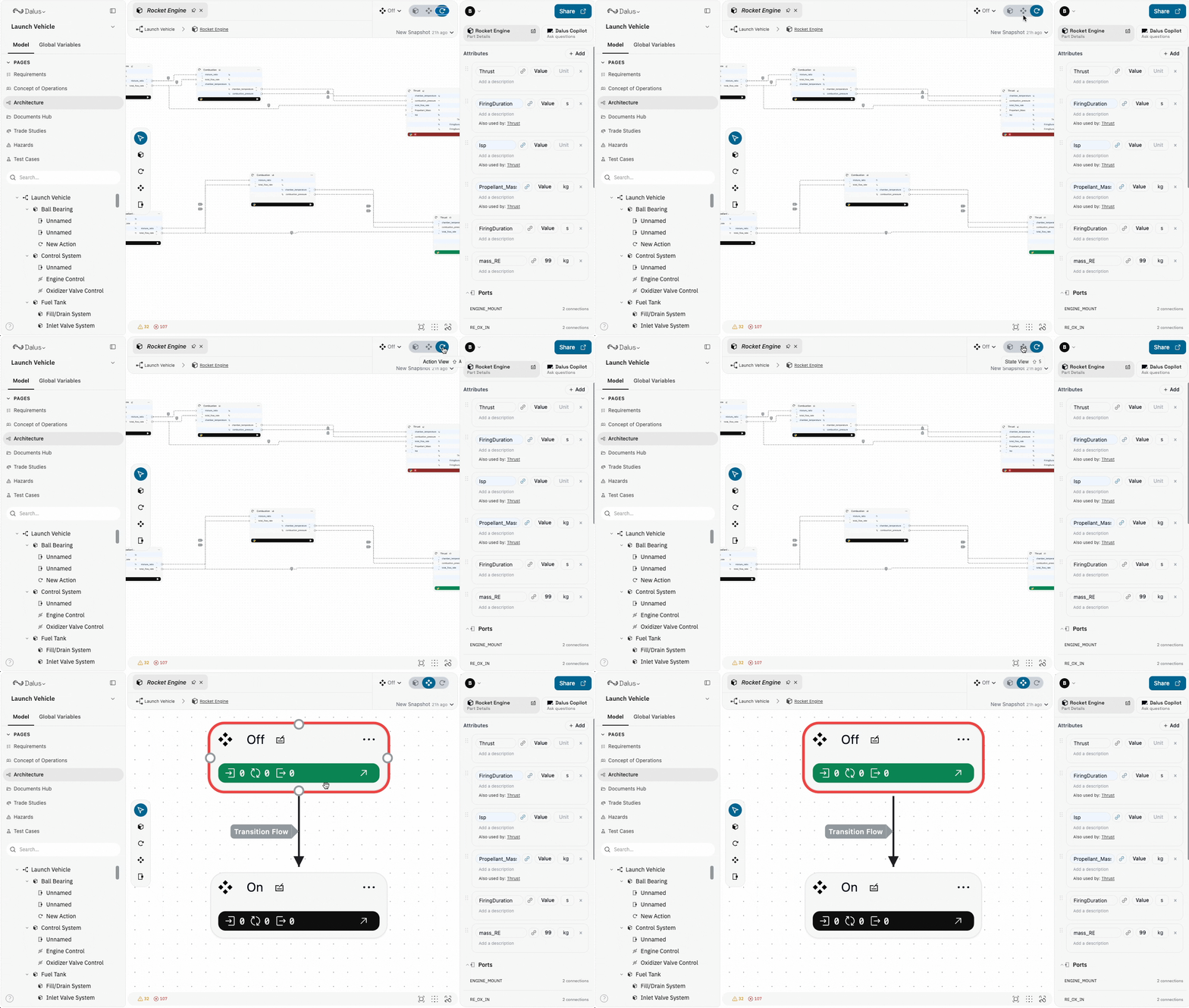
What are State Nodes
State nodes represent distinct operational modes or conditions of your system. Each state can have associated actions that execute at specific times:- Entry Actions: Execute when entering the state
- Do Actions: Execute continuously while in the state
- Exit Actions: Execute when leaving the state
Creating State Nodes
Create state nodes using the toolbar or keyboard: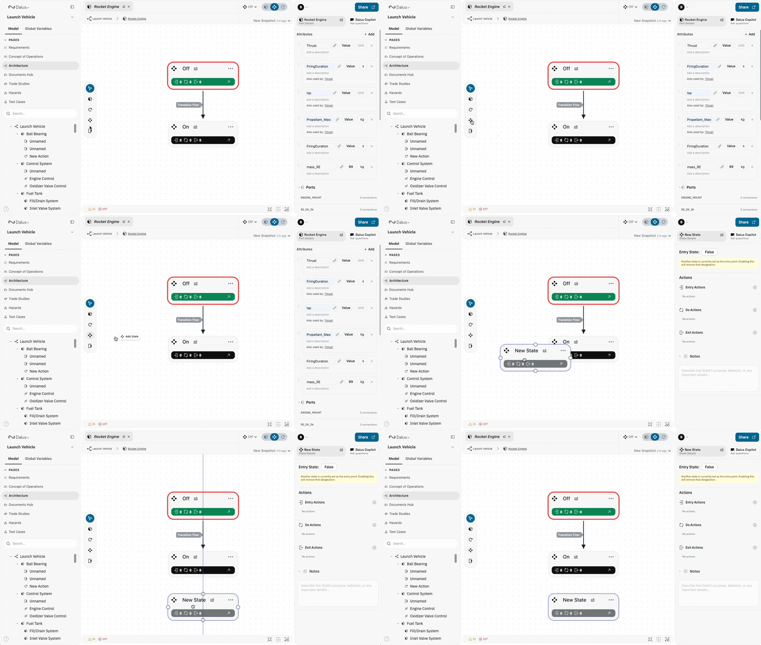
States must be created inside a Part (or inside another State for nested state machines). They cannot exist at the root level.
Idle, Powered_On, Transmitting, Emergency_Shutdown).
Double-click any state to open it in a new tab and define nested states or associated actions.
State Properties
When you select a state, the right sidebar displays:- Label: The state’s display name
- Description: Explanation of what this operational mode represents
- Entry Actions: Actions triggered on state entry
- Do Actions: Actions that run while in this state
- Exit Actions: Actions triggered on state exit
- Nested States: Sub-states for hierarchical state machines
- Notes: Additional documentation
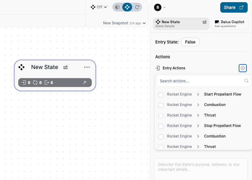
Assigning Actions to States
Link actions to state lifecycle events:- Select a state
- In the right sidebar, find Entry/Do/Exit Actions
- Click Add Action and select from available actions
- The action will execute at the appropriate time
Creating Transition Edges
Transition edges connect state nodes to define valid state changes. They represent the paths your system can take between operational modes.Creating Transitions
- Click and drag from one state node
- Connect to another state node
- Configure the transition in the right sidebar
- Self-loops: Return to the same state (for periodic actions)
- One-way: Only allow transition in one direction
- Bidirectional: Create two separate transitions for back-and-forth
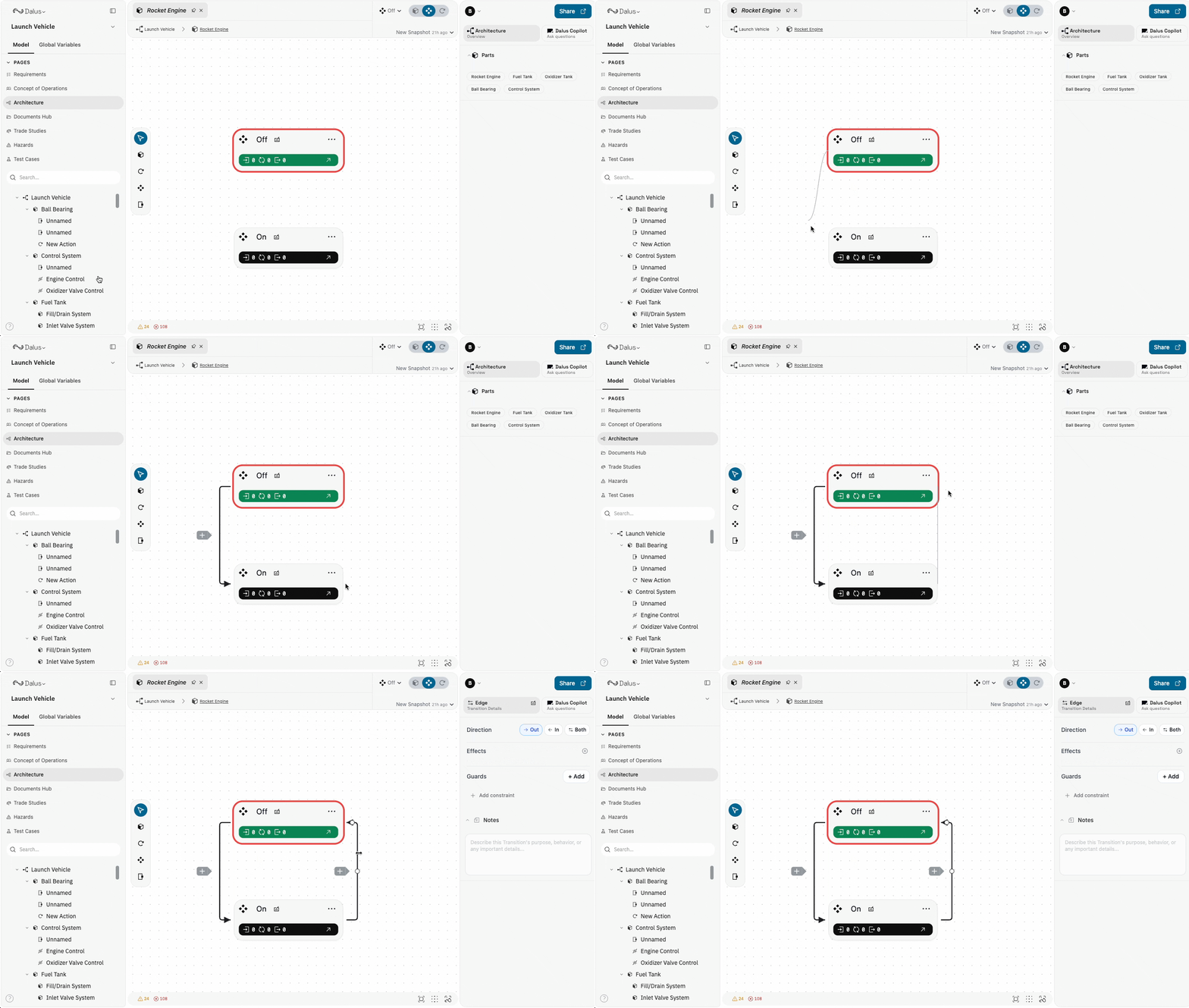
Transition Properties
When you select a transition, the right sidebar shows:- Label: Name or description of the transition
- Effects: Actions that execute during the transition
- Guards: Conditions that block the transition when true
- Triggers: Conditions or events that fire the transition
- Notes: Documentation about when/why the transition occurs
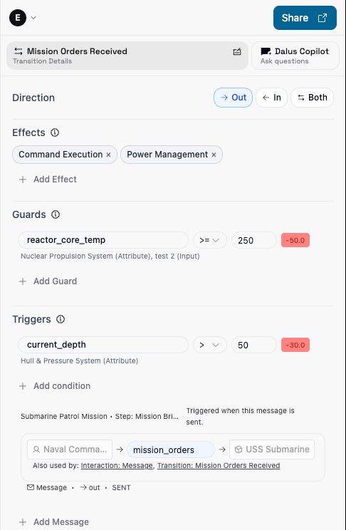
mission_orders message is sent or current_depth > 50 flips to true, as long as reactor_core_temp < 250. Upon triggering, it executes the Command Execution and Power Management actions and transitions us to Departing.
Transition Effects
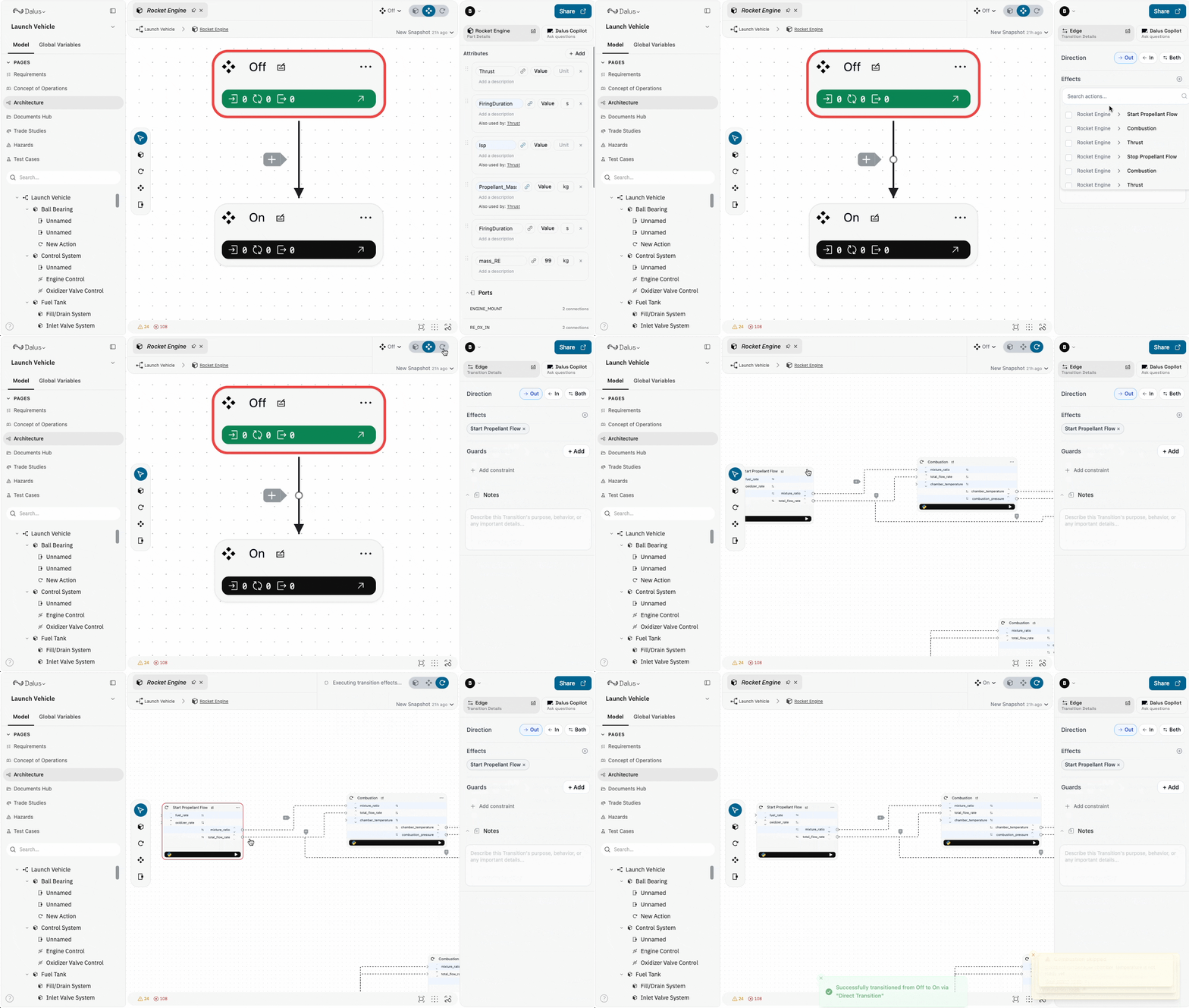
Assign actions as transition effects to execute computations when moving between states:- Select a transition
- In the right sidebar, find the Effects section
- Click Add Effect and select an action
- The action executes when the transition fires
Guards (blocking conditions)
Guards prevent a transition from firing. A guard is a constraint against a variable (for example:reactor_core_temp >= 250).
- If any guard evaluates to true, the transition is blocked.
- Use guards for “do not transition if…” safety or validity checks.
Triggers (conditions + mission messages)
Triggers define when a transition should fire automatically. A transition triggers when:- The part is currently in the transition’s source state, and
- All guards are false, and
- Any trigger flips from false → true.
- Condition triggers: Variable constraints (similar to guards) that fire the transition when they become true.
- Message triggers: Fire when a linked mission message is marked as
sentduring mission simulation. This is how Mission Planning can drive Architecture state machines.
State Machine Execution
Run your state machine to see behavior in action:- The system starts in an initial state
- Use the States Dropdown to trigger transitions
- Watch entry/do/exit actions execute
- Observe variable changes propagate through signals
View Modes
Toggle between views to focus on different behavioral aspects:
Switch views using the toggle buttons in the canvas toolbar.
Keyboard Shortcuts
Master these shortcuts for efficient behavior modeling:Using AI for Behavior Modeling
The Dalus AI Copilot accelerates behavior modeling tasks:Action Generation
Ask Copilot to create computational actions:- “Create an action to calculate orbital velocity from altitude”
- “Generate a data validation action for sensor inputs”
State Machine Design
Let AI design state machines:- “Create a state machine for the power management system”
- “Design states for the communication module’s operational modes”
Script Writing
Get help with Python scripts:- “Write a script to compute fuel consumption based on thrust and duration”
- “Help me create a filtering algorithm for noisy sensor data”
Signal Connections
AI can suggest proper signal routing:- “Connect the outputs of the Trajectory Calculator to the Guidance System”
- “What signals should connect these actions?”
Combining Structure and Behavior
Behavior lives inside structure. Best practices for integration:- Create the structural hierarchy first — Parts define where behaviors exist
- Add actions to the appropriate parts — Computations belong to the components that perform them
- Design state machines at the system level — States often orchestrate multiple parts
- Connect actions across parts via signals — Data flows follow the structural interfaces
- Link states to part lifecycle — Entry/exit actions should reflect physical system behavior
Essential Tips
- Plan data flow: Design signal connections before writing action scripts
- Use state machines: Organize complex behaviors into clear operational modes
- Test incrementally: Build and test actions individually before connecting them
- Document behavior: Use notes to explain action purposes and state meanings
- Monitor execution: Use simulation features to verify behavior logic
- Match semantics: When creating signals, always match by variable meaning, not position
- Keep scripts focused: Each action should do one thing well
- Use visualizations: Generate charts and tables to validate computational outputs
- Version your scripts: Use snapshots to save working configurations
Collaboration
Real-time collaboration features for behavior modeling:- Live Cursors: See where teammates are editing
- Simultaneous Editing: Multiple users can work on different actions/states
- Script Synchronization: Python scripts sync in real-time
- Execution Visibility: See when others run simulations