> ## Documentation Index
> Fetch the complete documentation index at: https://docs.dalus.io/llms.txt
> Use this file to discover all available pages before exploring further.
# Concepts
# Overview
Dalus provides a set of fundamental elements for modeling complex systems. These elements are organized into categories for structural modeling, behavioral modeling, and operational planning.
## Architecture Elements
| Element | Purpose |
| ------------------------------ | ------------------------------------------------------------------------------------------------------ |
| [**Part**](#parts) | Structural unit representing a component, subsystem, or module. Can be decomposed hierarchically. |
| [**Port**](#ports) | Entry or exit point on a Part's boundary where it interacts with other Parts. |
| [**Interface**](#interfaces) | Defines what flows between Parts through Ports—matter, information, energy, or mechanical connections. |
| [**State**](#states) | Represents a distinct mode a Part can be in at any given time. |
| [**Transition**](#transitions) | Defines allowed state changes and what Actions execute when the transition occurs. |
| [**Action**](#actions) | A function that a Part performs, with inputs, outputs, and executable code. |
| [**Signal**](#signals) | Connects Actions in sequence, propagating outputs to inputs and triggering execution. |
## Supporting Elements
| Element | Purpose |
| -------------------------------- | ----------------------------------------------------------------------------------------------------------- |
| [**Variable**](#variables) | Represents quantities with values and units—used for attributes, inputs/outputs, and connection properties. |
| [**Requirement**](#requirements) | Captures stakeholder needs with constraints that determine verification status. |
## Mission Planning Elements
| Element | Purpose |
| -------------------------------- | ----------------------------------------------------------------------------------- |
| [**Mission**](#mission-planning) | An operational scenario or use case that the system must support. |
| [**Actor**](#mission-planning) | An external entity (person, system, or environment) that interacts with the system. |
| [**Subject**](#mission-planning) | The system or subsystem being analyzed in the context of a use case. |
Coming from SysML v1? See the SysML v1 ⇄ SysML v2 ⇄ Dalus mapping.
## Variables
A **Variable** consists of a name, value, and unit (optional). They appear as:
* Part attributes (e.g., *mass: 200 kg*)
* Inputs and outputs on Actions (e.g., *voltage: 10 V*)
* Connections inside interfaces (e.g., *flow\_rate: 8 kg/s*, *T: 25 C*, *p: 90 psi*)
Variable values are defined by mathematical expressions, i.e. `1 + 2*(43^5)`, and can reference other variables by name, i.e. `total_mass = mass1 + mass2`.
## Requirements
A **Requirement** captures a stakeholder need or obligation that the system must satisfy.
Core properties:
* `level` – abstraction level (mission, system, subsystem, component)
* `name` – short, human-readable title
* `statement` – the requirement text expressed as a shall/should clause
* `constraints` – quantitative checks such as `mass < 100 kg`, each referencing a Variable, operator, and limit
* `status` – verification state derived from constraints (complete, failed, in progress)
### Verification
Requirement status is determined automatically:
* Constraints evaluate to *true* or *false* based on their referenced Variable
* A requirement is **complete** when all constraints are true, **failed** when any is false, **in progress** when variables lack values
* Actions can set Variables globally, updating constraint evaluations
Requirements are assigned to specific Parts to establish traceability.
## Parts
The **Part** is the fundamental structural element. A Part represents a self-contained portion of your system—hardware or software—that you treat as a black box.
Parts can be nested indefinitely to capture system decomposition:
* **Spatial decomposition** for hardware (assemblies, sub-assemblies, components)
* **Logical decomposition** for software (layers, services, modules)
Part properties are called **attributes**, which are Variables that belong to the Part.
 ## Ports
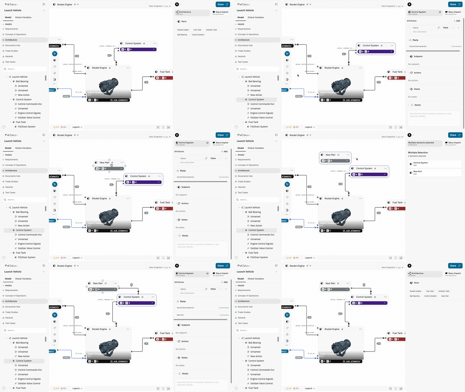
**Ports** are the exposed entry or exit points on a Part's boundary. They mark where the Part interacts with the outside world.
## Ports
**Ports** are the exposed entry or exit points on a Part's boundary. They mark where the Part interacts with the outside world.
 ## Interfaces
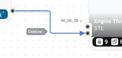
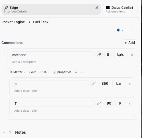
**Interfaces** define what flows between Parts through Ports. An Interface has a name, optional color, and one or more **Connections**—the individual flows of matter, information, energy, or mechanical load.
### Connections
A Connection captures:
| Field | Description |
| -------------- | ------------------------------------------------------------- |
| **Type** | Matter, Information, Energy, or Binding |
| **Direction** | Flow orientation (in, out, both) |
| **Subtype** | Optional detail (e.g., Ethernet, O2 gas, Electrical) |
| **Variable** | The numeric value and unit (e.g., 2 kg/s, 28 V) |
| **Properties** | Additional variables (e.g., frequency, temperature, pressure) |
## Interfaces
**Interfaces** define what flows between Parts through Ports. An Interface has a name, optional color, and one or more **Connections**—the individual flows of matter, information, energy, or mechanical load.
### Connections
A Connection captures:
| Field | Description |
| -------------- | ------------------------------------------------------------- |
| **Type** | Matter, Information, Energy, or Binding |
| **Direction** | Flow orientation (in, out, both) |
| **Subtype** | Optional detail (e.g., Ethernet, O2 gas, Electrical) |
| **Variable** | The numeric value and unit (e.g., 2 kg/s, 28 V) |
| **Properties** | Additional variables (e.g., frequency, temperature, pressure) |
 ## States
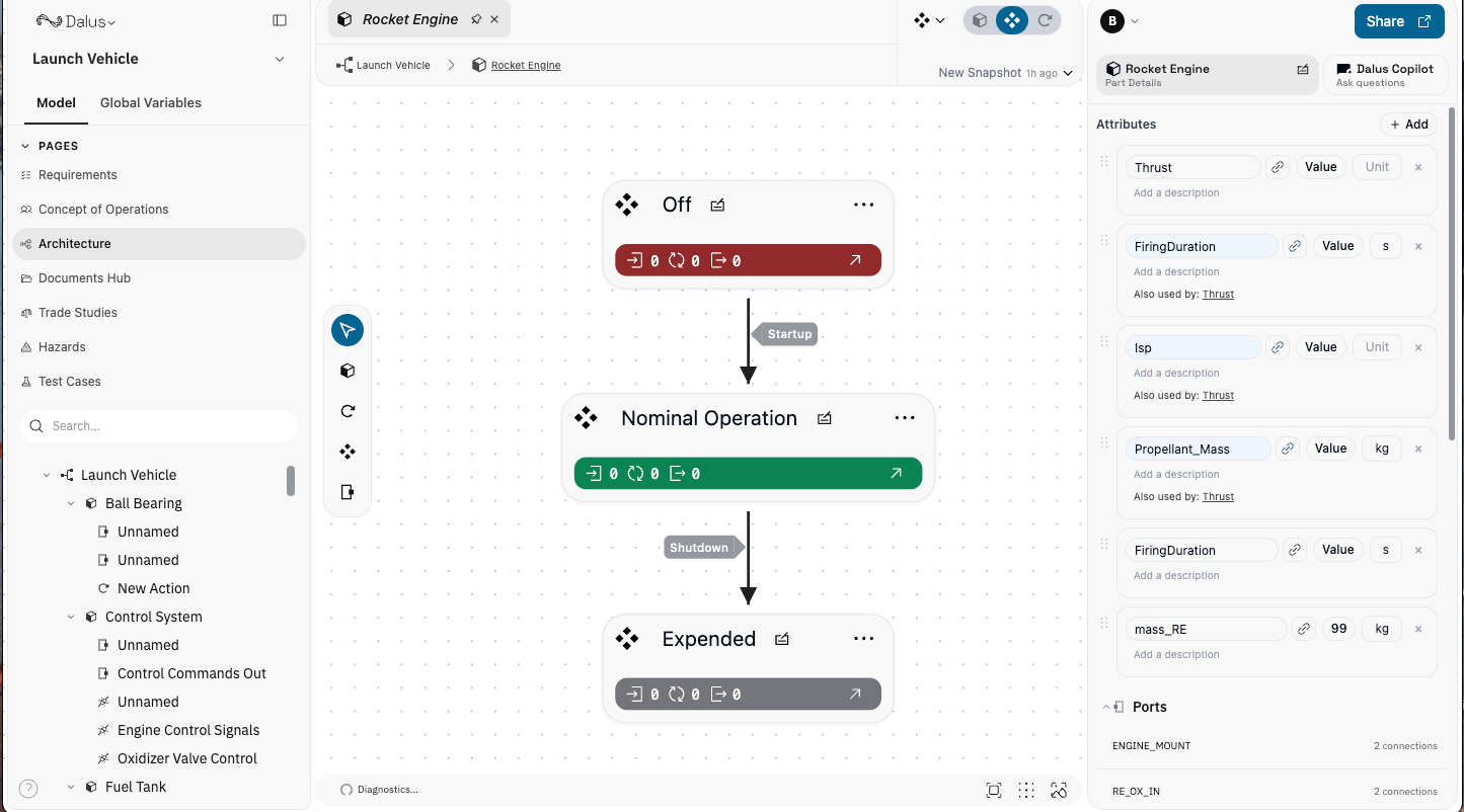
**States** represent the distinct modes a Part can inhabit during its lifecycle (e.g., *OFF*, *NOMINAL*, *SAFE MODE*).
To assign a State to a Part, add it inside that Part in the element tree.
## Transitions
A **Transition** defines which states can transition to other states and what happens when the transition occurs.
Create a transition by connecting two states on the canvas. Assign a direction and Actions (transition effects) to execute when triggered.
## States
**States** represent the distinct modes a Part can inhabit during its lifecycle (e.g., *OFF*, *NOMINAL*, *SAFE MODE*).
To assign a State to a Part, add it inside that Part in the element tree.
## Transitions
A **Transition** defines which states can transition to other states and what happens when the transition occurs.
Create a transition by connecting two states on the canvas. Assign a direction and Actions (transition effects) to execute when triggered.
 ## Actions
**Actions** are the functions that a Part performs. Each Action:
1. Consumes input variables
2. Runs a Python code snippet
3. Produces output variables
## Actions
**Actions** are the functions that a Part performs. Each Action:
1. Consumes input variables
2. Runs a Python code snippet
3. Produces output variables
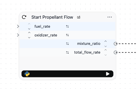 Actions can be chained so outputs feed into inputs of the next Action. Within Python you have global read/write access to every Variable in the model.
Each Action stores metadata:
* **description** – what the action does
* **success criteria** – expected outcomes
* **failure modes** – known failure scenarios
## Signals
A **Signal** connects Actions in sequence: it propagates output Variables from one Action to the inputs of the next and triggers execution. An Action fires only after all its inputs have been provided.
## Mission Planning
The Mission Planning (ConOps) view helps you model how your system will be used before diving into detailed architecture.
* **Mission** – An operational scenario or use case (e.g., "Launch sequence", "Emergency abort")
* **Actor** – An external entity that interacts with the system (e.g., "Operator", "Ground station", "Environment")
* **Subject** – The system or subsystem being analyzed
* **Interaction** – Connections between Actors and Subjects showing how they communicate
Use ConOps to capture stakeholder needs, operational scenarios, and system context before decomposing into detailed Parts and Interfaces.
## Conclusion
These concepts form the foundation for modeling systems in Dalus—from structural decomposition to behavioral modeling and requirements traceability.
If you haven't already, complete the [Quickstart](/get-started/quickstart) for a hands-on guide.
To learn more about the modeling language Dalus is based on:
* [SysML v2 Specification](https://www.omg.org/spec/SysML/2.0/Beta2/Language/PDF)
* Sandy Friedenthal's [SysML v2 Basics slide deck](https://www.omgwiki.org/MBSE/lib/exe/fetch.php?media=mbse:sysml_v2_transition:sysml_v2_basics-incose_iw-sfriedenthal-2024-01-28.pdf)
Start by identifying a clear goal for your model, then build only the components necessary to achieve that goal. Contact us at [founders@dalus.io](mailto:founders@dalus.io) for help.
The goal is not just a diagram, but a **single source of truth** for your system that you can analyze, simulate, and evolve with confidence.
Actions can be chained so outputs feed into inputs of the next Action. Within Python you have global read/write access to every Variable in the model.
Each Action stores metadata:
* **description** – what the action does
* **success criteria** – expected outcomes
* **failure modes** – known failure scenarios
## Signals
A **Signal** connects Actions in sequence: it propagates output Variables from one Action to the inputs of the next and triggers execution. An Action fires only after all its inputs have been provided.
## Mission Planning
The Mission Planning (ConOps) view helps you model how your system will be used before diving into detailed architecture.
* **Mission** – An operational scenario or use case (e.g., "Launch sequence", "Emergency abort")
* **Actor** – An external entity that interacts with the system (e.g., "Operator", "Ground station", "Environment")
* **Subject** – The system or subsystem being analyzed
* **Interaction** – Connections between Actors and Subjects showing how they communicate
Use ConOps to capture stakeholder needs, operational scenarios, and system context before decomposing into detailed Parts and Interfaces.
## Conclusion
These concepts form the foundation for modeling systems in Dalus—from structural decomposition to behavioral modeling and requirements traceability.
If you haven't already, complete the [Quickstart](/get-started/quickstart) for a hands-on guide.
To learn more about the modeling language Dalus is based on:
* [SysML v2 Specification](https://www.omg.org/spec/SysML/2.0/Beta2/Language/PDF)
* Sandy Friedenthal's [SysML v2 Basics slide deck](https://www.omgwiki.org/MBSE/lib/exe/fetch.php?media=mbse:sysml_v2_transition:sysml_v2_basics-incose_iw-sfriedenthal-2024-01-28.pdf)
Start by identifying a clear goal for your model, then build only the components necessary to achieve that goal. Contact us at [founders@dalus.io](mailto:founders@dalus.io) for help.
The goal is not just a diagram, but a **single source of truth** for your system that you can analyze, simulate, and evolve with confidence.